Delving into the Intricacies of Ceiling Fan Lighting Diagrams
Ceiling fans are ubiquitous fixtures in modern homes, providing both ventilation and illumination. Understanding the intricacies of ceiling fan lighting diagrams is crucial for proper installation and maintenance. This comprehensive guide will delve into the essential aspects of these diagrams, empowering you with the knowledge to tackle any ceiling fan lighting project with confidence.
Decoding the Wiring Diagram
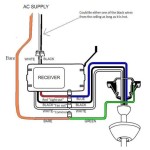
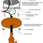
The wiring diagram is the cornerstone of a ceiling fan lighting diagram. It depicts the electrical connections between the fan's components, including the motor, light fixture, and switch. The diagram typically includes color-coded wires, each designated for a specific function. Understanding these colors is essential for accurate wiring.
Motor Wiring: The Powerhouse of the Fan
The motor is the driving force behind the fan's rotation. Typically, black wires carry the power from the switch to the motor, while white wires provide a neutral path. Green or bare wires act as the ground connection, ensuring electrical safety.
Light Fixture Wiring: Illuminating the Space
Ceiling fan lighting diagrams also include wiring for the light fixture. Black wires typically connect to the hot terminal on the light fixture, while white wires connect to the neutral terminal. Ground wires remain green or bare and connect to the fixture's grounding screw.
Switch Wiring: Controlling the Fan and Light
The switch controls both the fan and the light. In most diagrams, black wires connect the switch to the power source, while white wires connect to the switch's common terminal. Additional wires may be present for controlling separate light or fan speeds.
Understanding Terminal Designations
Ceiling fan lighting diagrams often use letter designations for terminals within the fan and light fixture. These designations indicate the purpose of each terminal, such as "L" for line (power), "N" for neutral, and "G" for ground.
Interpreting Symbolism
In addition to wiring diagrams, ceiling fan lighting diagrams may include symbols to represent components or connections. For instance, a light bulb symbol represents the light fixture, while a switch symbol indicates the fan's switch. Understanding these symbols is essential for interpreting the diagram correctly.
Troubleshooting and Maintenance
In case of any issues with the ceiling fan or light fixture, refer to the lighting diagram for troubleshooting guidance. The diagram can pinpoint the specific component or connection that may be causing the problem. Regular maintenance, such as cleaning and lubricating the fan, can also be facilitated by the diagram's detailed information.
Conclusion
Understanding ceiling fan lighting diagrams is not only essential for installation but also for ongoing maintenance and troubleshooting. By deciphering the wiring, terminal designations, and symbols, you can confidently navigate any ceiling fan lighting project, ensuring a well-lit and efficiently operating indoor environment.

Wiring A Ceiling Fan And Light With Diagrams Ptr

How To Wire A Ceiling Fan Temecula Handyman

Wiring A Ceiling Fan And Light With Diagrams Ptr

Ceiling Fan Wiring Diagram

Ceiling Fan Wiring Diagram Single Switch

Wiring A Ceiling Fan And Light With Diagrams Ptr

Ceiling Fan Wiring Diagram Power Into Light

Replacing A Ceiling Fan Light With Regular Fixture Jlc

Replace Light Fixture W Ceiling Fan R Askanelectrician
Replacing A Ceiling Fan Light With Regular Fixture Jlc
Related Posts

