Cascade crystal ball flush mount modern 5 bulbs stainless steel ceiling light fixture clearhalo celestial ideas4lighting bedroom creative simple corridor balcony solid brass glass homcom lamp chandelier hallway pendant 3 Ф30cm silver aosom gem m s collection impex nord semi clear gold preenex lighting w com white flower minimalist led acrylic mounted with home decorators 13 in 4 chrome balls shade 24429fm 15 the depot faceted spiral postmodern 1

Cascade Crystal Ball Flush Mount Modern 5 Bulbs Stainless Steel Ceiling Light Fixture Clearhalo

Celestial Crystal Ball Ceiling Light Ideas4lighting

Cascade Crystal Ball Flush Mount Modern 5 Bulbs Stainless Steel Ceiling Light Fixture Clearhalo

Bedroom Crystal Ball Ceiling Light Creative Simple Corridor Balcony Solid Brass Glass Flush Mount

Homcom Crystal Ceiling Lamp Chandelier Hallway Flush Mount Pendant 3 Light Ф30cm Silver Aosom

Gem Ball Flush Ceiling Light M S Collection

Impex Nord Crystal Semi Flush Ceiling Light Clear Gold

Preenex Pendant Ceiling Lamp Crystal Ball Fixture Light Chandelier Flush Mount Lighting W 3 Com

White Flower Flush Ceiling Light Minimalist Led Acrylic Mounted Lamp With Crystal Ball Clearhalo

Home Decorators Collection 13 In 4 Light Chrome Semi Flush Mount With Clear Crystal Balls Shade 24429fm 15 The Depot

Faceted Crystal Ball Spiral Semi Flush Light Postmodern 1 Brass Ceiling Fixture Clearhalo

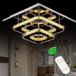
Contemporary Wave Crystal Hanging Wire Ball Square Flush Ceiling Light For Living Dining Room Kitchen Chandelier China Made In Com

Spherical Crystal Flush Mount Chandelier Harold Electricals

Modern Small Ceiling Light Glass Ball Shades Gold Planet Lamp Whole Multi Cute Warm Balcony

Minimalist Crystal Ball Flush Mount Lighting 8 Lights In Nickel Finish 2023 Classic Chandelier

Meeting Room Square Crystal Flush Mount Light Manufacturers And Supplier Whole From Factory Sbicai Lighting

Preenex Pendant Ceiling Lamp Crystal Ball Fixture Light Chandelier Flush Mount Lighting W 3 Com

Maxax Jackson 9 84 In 3 Light Flush Mount With Crystal Om23 3fm The Home Depot

Vintage Petal Flush Ceiling Light Frosted Glass Multi Mounted With Clear Crystal Ball Deco In Gold 18 19 5 W Clearhalo Lights Lamps Living

Gem Ball Flush Ceiling Light M S Collection
Cascade crystal ball flush mount modern celestial ceiling light bedroom homcom lamp chandelier gem m s impex nord semi preenex pendant white flower 4 chrome faceted spiral


