Hunter Ceiling Fan 4 Wiring Schematic: Essential Aspects
Hunter ceiling fans are renowned for their reliable performance and stylish designs. Understanding the wiring schematic is crucial for proper installation and maintenance of your fan. This guide will delve into the essential aspects of the Hunter ceiling fan 4 wiring schematic, providing you with a comprehensive understanding of the electrical connections.
Terminal Box and Wires
The terminal box, located at the top of the fan, houses the electrical connections. It typically contains three wires: black (hot), white (neutral), and green (ground). In addition, there may be two or four smaller wires for fan speed control and light installation.
Power Source Connection
The black wire from the fan terminal box should be connected to the black wire from the power source (breaker panel or outlet). Likewise, the white wire from the fan should be connected to the white wire from the power source. Finally, the green ground wire from the fan should be connected to the green or bare copper ground wire from the power source.
Fan Speed Control Wires
For fans with multiple speed settings, there will be two or four smaller wires, typically colored blue, brown, orange, or yellow. These wires connect the fan motor to the speed control switch, allowing you to adjust the fan's speed.
Light Installation Wires
If your fan includes a light fixture, there will be two additional wires, usually black and white, for the light connection. The black wire from the light fixture should be connected to the black wire from the ceiling fan terminal box, while the white wire from the light fixture should be connected to the white wire from the fan.
Diagram Interpretation
The Hunter ceiling fan 4 wiring schematic typically includes a diagram that represents the electrical connections. It can be helpful to study the diagram carefully and understand how each wire is connected to the other components.
Safety Considerations
It is essential to follow the wiring schematic carefully and ensure all electrical connections are secure. Always turn off the power at the breaker panel before working on the fan, and consult an electrician if you are unsure about any aspect of the installation or wiring.
Conclusion
Understanding the Hunter ceiling fan 4 wiring schematic is crucial for a safe and successful installation. By following the steps outlined in this guide, you can ensure your fan operates correctly and provides years of comfortable and efficient air circulation.

Wiring A Ceiling Fan And Light With Diagrams Ptr

Hunter Fans Internal Wiring And Data

Wiring A Ceiling Fan And Light With Diagrams Ptr

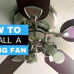
Installation Instructions For Hunter Ceiling Fan

Bypass Hunter Fan Receiver Doityourself Com Community Forums

Ceiling Fand Wiring Diagrams

Ceiling Fand Wiring Diagrams

Fan Wiring Diagrams Etc

Wiring A Ceiling Fan And Light With Diagrams Ptr

Hunter Fans How To Install Your Ceiling Fan Cpo S
Related Posts