Essential Aspects of Ceiling Fan Light Pull Switch Wiring Diagram
Navigating the complexities of ceiling fan light pull switch wiring can be a daunting task, especially for the uninitiated. However, with a clear understanding of the underlying principles and a well-structured wiring diagram, the process becomes much more manageable.
This comprehensive guide will delve into the essential aspects of ceiling fan light pull switch wiring diagrams, providing a step-by-step explanation of each component and its function. By the end, you'll have the knowledge and confidence to tackle any ceiling fan light pull switch wiring project with ease.
Understanding the Diagram
A ceiling fan light pull switch wiring diagram is a visual representation of the electrical connections between the ceiling fan, light fixture, and pull switch. It outlines the flow of electricity from the power source to the fan and light, ensuring proper operation and safety.
A typical ceiling fan light pull switch wiring diagram includes the following elements:
- Power source (usually a household electrical circuit)
- Ceiling fan motor
- Light fixture
- Pull switch
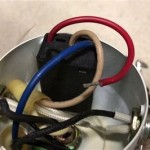
- Wires (black, white, red, blue, ground)
Color-Coded Wires
The wires used in ceiling fan light pull switch wiring are color-coded to indicate their purpose and provide a consistent method of connection. The most common wire colors and their functions are:
- Black: Hot wire (carries current from the power source)
- White: Neutral wire (completes the circuit)
- Red: Traveler wire (controls fan speed)
- Blue: Traveler wire (controls light fixture)
- Green or bare copper: Ground wire (provides a safety pathway for excess current)
Connecting the Wires
The specific wiring connections will vary depending on the type of ceiling fan and light fixture you have. However, there are some general guidelines that apply to most installations:
- Connect the black wire from the power source to the black wire from the fan motor.
- Connect the white wire from the power source to the white wire from the fan motor and the neutral terminal on the light fixture.
- Connect the red traveler wire to the red wire on the pull switch.
- Connect the blue traveler wire to the blue wire on the pull switch.
- Connect the green ground wire to the green ground wire on the fan motor, light fixture, and pull switch.
Testing the Wiring
Once the wiring is complete, it's crucial to test the connections to ensure everything is working correctly. Using a multimeter or voltage tester, check for continuity between the appropriate terminals and wires. If there are any breaks or loose connections, troubleshoot and repair them before operating the ceiling fan.
Remember, electrical work can be hazardous if not performed correctly. If you are unsure about any aspect of the wiring process, it's highly recommended to consult with a qualified electrician.

3 Sd Ceiling Fan Pull Chain Switch Wiring Pickhvac

Wiring A Ceiling Fan And Light With Diagrams Ptr

Ceiling Fan Light Switch Ear Ze 109 Two Wire With Pull For Fans 2pcs Sil Fruugo Sa

Pull Chain Sd Control Casablanca Fan Repair

Ceiling Fan Pull Chain And Wall Switch Wiring With Diagrams

Wiring A Ceiling Fan And Light With Diagrams Ptr

Ze 110 Zing Ear Pull Chain Switch For Ceiling Fan

Ceiling Fan Switch For Zing Ear Ze 110 3 Way Wire Pull Chain Light

Zing Ear Ze 268s6 Wiring Instructions Ceilingfanswitch Com

How To Wire A Ceiling Fan Control Using Dimmer Switch
Related Posts

